Fuse selection process
Technical Paper
Fuse selection process
Properly selected fuses prevent accidents by breaking abnormal currents when they flow through electric circuits. Improper selection, however, can result in nuisance operations, continued flow of abnormal currents, generation of smoke and/or fire, and other dangers.
If you are facing difficulties such as “I don’t have enough time to select!” or “I’m not sure how to select!”, please feel free to contact SOC for technical advice or questions regarding selection considering temperature conditions, margins, or selection evaluation based on waveform data and circuit conditions.
Safety precautions when selecting fuses
■ What is the voltage of the circuit the fuse will be used in?
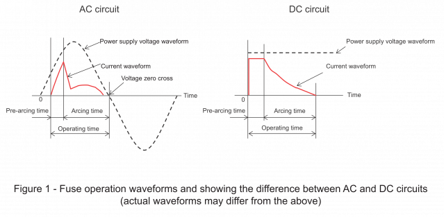
Make sure to select a fuse that has a rated voltage higher than the voltage of the circuit.
The rated voltage of a fuse is the maximum voltage at which the fuse can safely interrupt an abnormal current. If the voltage of the circuit is higher than the fuse’s rated voltage, there is a danger the fuse may be destroyed as shown below. Please exercise caution.
■ Will the fuse be used in an AC circuit or a DC circuit?
Only select DC rated fuses for DC circuits, and AC rated fuses for AC circuits.
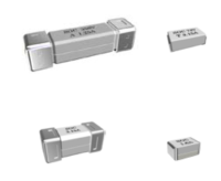
For AC circuits, there is a tendency for arc discharges to be extinguished when the power supply voltage goes to zero as shown in Figure 1 below. Caution should be exercised regarding use of DC circuits as DC voltage does not go to zero, and therefore there is the risk that an arc discharge may not be extinguished which may result in destruction of the fuse.
Therefore, due to the difference in circuit characteristics for AC and DC circuits, mistakenly using an AC fuse in a DC circuit or a DC fuse in an AC circuit may cause an accident.
■ What is the power factor / time constant of the circuit in which the fuse is to be installed?
The amount of the inductance of the circuit relates to the magnitude of the power factor or the time constant. When interrupting an abnormal current in a circuit with a large inductance, an arc voltage greater than that of the power supply may occur, and the fuse may be unable to safely break the current. The larger the inductance, the greater the arc energy generated at the fuse. The fuse is destroyed if it cannot withstand the arc energy.
When selecting fuses, please confirm that the fuse you have selected can safety clear abnormal currents in the equipment in which it is to be used.
■ How will the fuse be mounted?
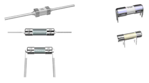
(1) Mounting directly to a wiring circuit board
a) Surface mount type
b) Terminals passed through holes in a wiring circuit board (pin terminals, lead terminals, and others)
(2) Mounting a fuse in a fuseholder (or clips)
![]()
(3) Directly bolted to a circuit
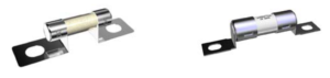
Please contact us for development of custom-designed fuses based on your shape and dimensional requirements.
■ How large current will be passed through the circuit the fuse will be used in?
A rated current is defined for each fuse, and this value is marked on it. Understanding the following circuit currents (including their waveforms) is important for selecting the appropriate rated current and rated breaking current *1 for a fuse in order to prevent nuisance operations and ensure the fuse is able to interrupt abnormal currents.
・Steady-state current
・Inrush current
・Abnormal current
*1 “Rated breaking capacity” is used in IEC 60127 (Miniature fuses) series, “interrupting rating” in the UL/CSA 248 series (Low-voltage fuses), and “rated breaking capacity” in JIS C 6575 (Miniature fuses) series, but all of these refer to the rated breaking current.
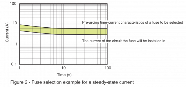
(1) Evaluation of a steady-state current
In order to avoid nuisance operation over long-term use, please select a fuse which has pre-arcing time-current characteristics *2 such that the fusing current is sufficiently larger than the steady-state current (root mean squared value) of the actual circuit in which the fuse will be installed. Figure 2 shows an example of the necessary difference (margin) between fusing current and actual circuit current.
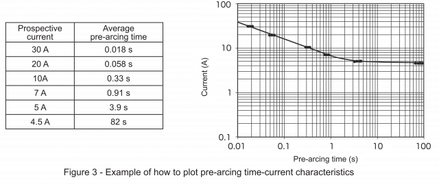
*2 Pre-arcing time-current characteristics:
As shown in Figure 3, pre-arcing time-current characteristics are created from the average pre-arcing time values for a number of constant currents. These are not guarantees of a fuse’s characteristics. This current is a current that would flow in the circuit if a fuse were replaced by a link of negligible impedance (prospective current).
(2) Evaluation of an inrush current
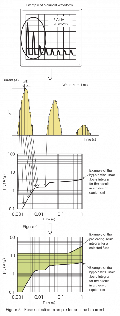
Generally it is not possible to evaluate inrush currents with pre-arcing time-current characteristics, since the peak values of inrush currents change dramatically with time. However, it is possible to evaluate the occurrence of nuisance operations by comparing the circuit’s Joule integral (Im2t, the integral of the square of the instantaneous current passed through the circuit over a certain time interval) with the pre-arcing Joule integral of the fuse (If 2t) in the short-time range where heat release from fuse-element to fuse body or fuse-terminations is not large.
Evaluation process
i) Repeatedly measure the current waveform of the circuit from when the equipment is powered on (inrush current) to the steady-state current.
ii) Discharge the remaining electric charge in the circuit’s capacitor and measure the current waveform. If there is a component like a thermistor with a resistance that changes depending on the temperature, measure the current waveform at the minimum resistance.
iii) Based on the measured current waveform, calculate the circuit’s Joule integral (Im2t) for each time. For example, the circuit’s Joule integral is calculated as follows when you have the Joule integral for 0.01 s and the sampling interval ⊿ t is equal to 0.001 s. Note that the instantaneous value of the current that flows through the circuit is represented by im(t). In actual practice, an even smaller sampling interval is used. A larger value was selected to explain the process. 0.01 s divided by 0.001 s is equal to 10. Therefore:
![]()
iv) Calculate the Joule integral for each time and plot the values on a graph as in Figure 4.
v) As in Figure 5, plot the graph with the circuit’s maximum Joule integral and the fuse’s pre-arcing Joule integral as functions of the time. In order to prevent nuisance operation, the relationship of maximum circuit Joule integral ≦ fuse pre-arcing Joule integral is always necessary, and in order to prevent nuisance operations caused by aging, it is necessary to select fuses with sufficient margin (for example, the shaded region in Figure 5). As the necessary margin differs depending on the usage conditions, it is necessary to perform evaluations in the actual equipment the fuse will be used in.
(3) Evaluation of an abnormal current
Measure the maximum possible abnormal current and select a fuse with a rated breaking current that can interrupt that abnormal current. Additionally, the minimum possible abnormal current should also be measured. In the comparatively short-time region, the fuse’s Joule integral shall be less than or equal to the Joule integral of the circuit when the minimum abnormal current flows through it. In the comparatively long-time region, the fuse’s minimum pre-arcing current shall be less than or equal to the abnormal current. The judgement whether or not these two relationships are fulfilled, depending upon the protection conditions at what point and over what time the abnormal current is required to be interrupted, can be difficult in most cases. Therefore it is both necessary and important to confirm whether the fuse can safely interrupt the abnormal current in the actual application.
Before final fuse selection, always test the proposed fuse in your actual equipment to ensure that the fuse satisfies all your operational and safety requirements. Please contact your local SOC sales representative for help in selecting fuses.
■ Explanation of rated current
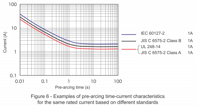
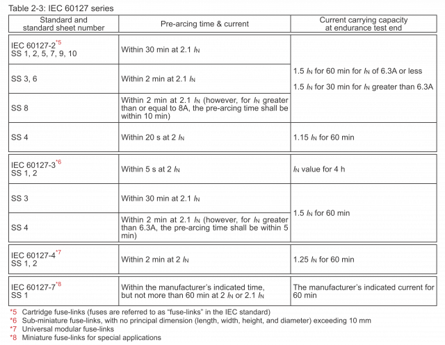
The requirements stipulated by each standard differ even among fuses with the same rated current, and each standard specifies pre-arcing (operating) times for multiples of the rated current (IN). In other words, pre-arcing time-current characteristics differ depending on the standard even when the rated current is the same.
On July 1, 2013, the Ministry of Economy, Trade and Industry (hereinafter called “METI”) Order establishing technical requirements for electrical appliances and materials was completely revised (with implementation from January 1, 2014) in order to change detailed specification requirements to safety performance requirements. The third table appended to the order prior to the revision (hereinafter called the “prior technical requirements”) is, at the current moment, approved to be used as one of the criteria for safety performance requirements for fuses according to the interpretation of the Ministerial Order. Specifications stipulated in the prior technical requirements for miniature fuses have been partially modified and incorporated into the JIS C 6575 (Miniature fuses) series step by step, taking into consideration consistency with the IEC 60127 series.
Within the JIS C 6575 series, specifications in the standard sheets containing the letter “J” are based on the prior technical requirements, while those with only Arabic numerals are based on the IEC standard. Revision of JIS standards can take a long time, and new versions may be delayed in some cases.
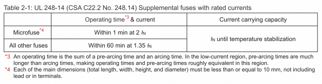
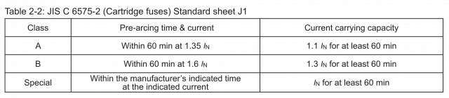
Tables 2-1, 2-2, and 2-3 show examples of minimum fusing currents and pre-arcing/operating times stipulated by different standards.
■ Time-current characteristics
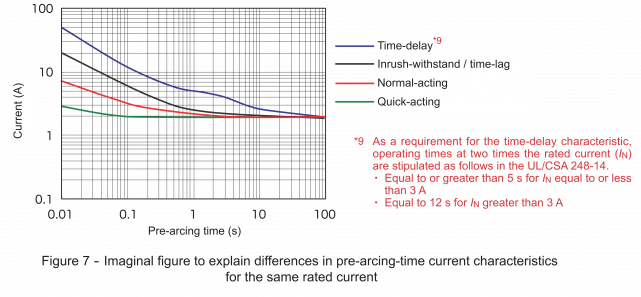
As per Figure 7, it is possible to design fuses having the same rated current, but with differing pre-arcing time-current characteristics. Please consult with SOC sales representatives when it is necessary to prevent nuisance operation due to an inrush current, or when an abnormal current should be interrupted more quickly.
■ Rated breaking current
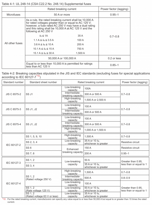
The rated breaking current is the upper limit value of prospective current that a fuse is capable of safely breaking under test conditions defined in a standard. Generally, breaking capacity tests are conducted using a circuit with a voltage 1–1.05 times the rated voltage of the fuse. As shown in Table 4-1 and 4-2, values of the rated breaking current differ depending on the standard. The lower limit value of current which a fuse can safely break is referred to as the minimum breaking current. For fuses with a minimum breaking current that is greater than the minimum fusing current, care should be taken as it cannot protect against overload currents between the minimum fusing current and minimum breaking current.
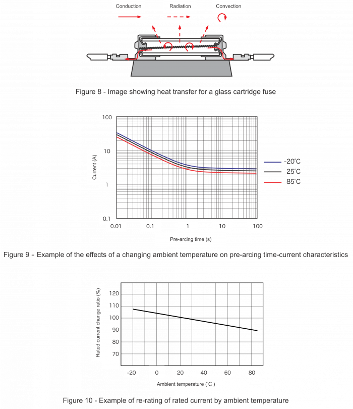
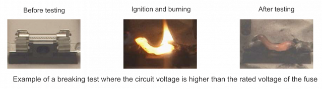
■ What is the fuse’s ambient temperature?
A fuse will operate when the temperature of the fuse-element exceeds the melting point of the metal it is comprised of, due to Joule heating caused by overcurrents. The temperature of the fuse-element is strongly influenced by heat dissipation. As can be imagined from Figure 8, heat dissipation differs according to the heat conductivity of the surrounding components, including fuse clips, fuseholders, wiring, and the circuit board, as well as the ambient temperature conditions. The pre-arcing time-current characteristics, for example, vary depending on ambient temperature conditions as in Figure 9. Therefore it is essential for final equipment testing to be conducted with the end application subjected to actual mechanical, electrical, and ambient conditions in order to assure achievement of satisfactory results and desired reliability. The effect of ambient temperature on pre-arcing time-current characteristics can be confirmed by temperature re-rating as shown in Figure 10. Please contact your SOC sales representative for temperature re-rating information.