


Fuse Basics & Recommendations
Technical paper
Fuse Basics & Recommendations
Principle of fuse operation
When high current unexpectedly flows into an electric circuit, the circuit, interconnect, or power supply may break, smoke, or start a fire as illustrated in Fig. 1(a).
In order to prevent such an accident, one can rely on fuses (Fig. 2).
When the current flowing through the circuit remains within the ordinary range, a fuse can be regarded as a low-resistance conductor.
On the other hand, once the current exceeds the pre-designed threshold level, fuses blow to keep the circuit, interconnect, or power supply intact as illustrated in Fig. 1(b).
This is called the “fuse operation”.
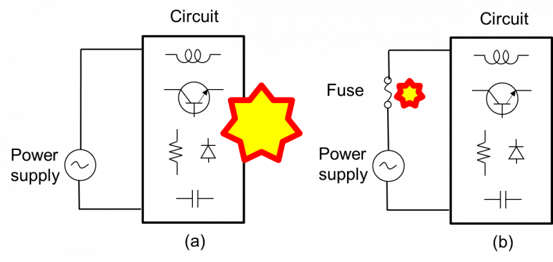
Figure 1 Electric circuit (a) without and (b) with a fuse in between power supply and circuit
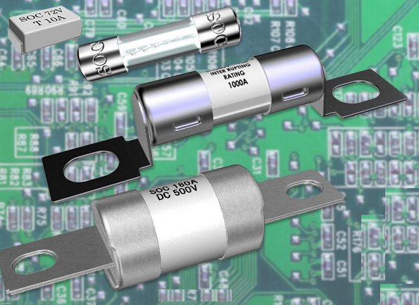
Figure 2 Examples of fuses
What is the operating principle of a fuse?
There is a hint in the above, “a fuse can be regarded as a low-resistance conductor”.
Since the electric resistance of the fuse is much lower than that of the load circuit, the fuse under normal circuit conditions functions as a low resistance conductor.
Still, the fuse resistance is designed higher than other conductors such as the electric wires or interconnects in the circuit.
Heat is generated when current flows through a resistor (an electric fuse, in this case) by the Joule heating mechanism, which is proportional to the product of the square of the current and the resistance.
The heat generated will escape to the surroundings, so the fuse will not get very hot as long as it is properly selected and the current stays within the ordinary range.
On the other hand, the situation is different when the current exceeds the limit.
In that case, a lot of heat proportional to the square of the electric current is generated and the temperature rises.
In addition, as the temperature rises, the electrical resistance of the fuse also rises, further increasing heat generation and raising the temperature significantly.
That is because the Joule heating, as described above, increases in proportion to the electric resistance.
That situation is schematically shown with the blue solid line in Fig. 3.
The vertical axis is temperature, sky blue is room temperature and red at the upper end of Fig. 3 is the temperature at which the fuse melts to blow.
The horizontal axis is the current flowing through the fuse.
The temperature stays within the blue zone and the fuse will not blow or melt with the low current in the range denoted by “Normal” in Fig. 3.
On the other hand, the temperature exceeds upper end of the graph so that the fuse will blow in the “Fuse-operating” range.
“Intermediate” range is in between the “Normal” and “Fuse-operating” ranges.
Fuse will not blow soon with current in this range, but may blow after repeated or prolonged flow of current in this range.
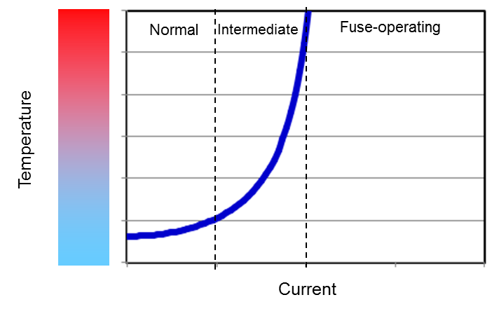
Figure 3 Schematic diagram of the relationship between fuse temperature and flowing current
Please look at Fig. 1(b) again.
The power supply is the source of electric energy.
Once high current flows, the fuse will operate to disconnect the circuit from the power supply, thus keeping the safety of the circuit.
When supplying electricity to multiple circuits from one power source, please insert fuses for each circuit, not only near the power source but also in between the branch point and each circuit as shown in Fig. 4.
If you select the fuses to be inserted correctly, when high current unexpectedly flows in circuit 1, the fuse between the branch point and circuit 1 will blow, but the main fuse in the immediate vicinity of the power supply will remain conducting, so that the circuits 2 and 3 will be kept energized.
This means that, for example, even if an auxiliary device (circuit 1) mounted on an automobile breaks, another important device (circuit 2 or circuit 3) that controls the car driving remains in operation.
Or, more generally, it helps to ensure that even in the case when one of the equipments fails, all the other equipments do not stop.
If the abnormal current originating from a failure of circuit 1 is not high enough to blow the fuse f0, f1 with a rated current smaller than f0 will blow so that circuit 1 can still be protected.
In order to take advantages of these effects, the underlined “select the fuse to be inserted correctly” is very important.
The fuse f1 between the branch point and circuit 1 needs to be selected so that it blows before the main fuse f0 in the immediate vicinity of the power supply blows when abnormal current flows through the circuit 1.
The ratings of other components than fuses, such as resistors and capacitors, represent the upper limits of the power or voltage range at which those components can be used without damage.
On the other hand, the “rated current” of a fuse indicates that it will blow in a specified time if current exceeds several times of it.
The role of fuse is to blow, or break.
If too much emphasis is placed on either breaking or not breaking, the fuse cannot function properly.
We provide waveform evaluation services so that you can “select the fuse correctly”.
Please do not hesitate to contact us.
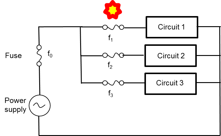
Figure 4 Example of how to place fuses when multiple circuits are connected to one power supply
Comparison of fuse and other over-current protection devices
There are various devices other than fuses that protect circuits from abnormal currents.
Below in Table I are the representative types and their respective functions and characteristics.
Please select the most suitable device according to your application.
There are many factors to consider when choosing: such as size, cost, required specifications and available product lineup.
Table I Devices that protect circuits from abnormal currents

Advantages and features of electric fuses
(1) Safety
A fuse is simple in structure.
Therefore, if a short-circuit accident occurs in which very high current could flow (unless the fuse is inserted), the fuse blows in a shorter time than the current value reaches its maximum, and the current flowing in the circuit is kept lower.
This is so-called “current limiting effect” of fuse shown in Fig. 5 below.
The horizontal axis is time and the vertical axis is current.
The blue line represents the current that should flow if the fuse is not inserted, while the red line is the current that actually flows when the fuse blows and the current limiting effect appears.
By using a fuse in your circuit, you can benefit from the current limiting effect to minimize damages.
After the circuit breaker trips and interrupts high current, the breaker switch is often reset for reuse.
However, it is not always safe to reset a circuit breaker switch that has once experienced high current.
Tripping of the breaker means that something may be wrong with the circuit.
In addition, the invisible part of the breaker may have already been damaged by the high current that has flowed once.
That damage can cause a serious accident.
In those respects, a fuse is safer, as a fuse cannot be reused once it has blown.
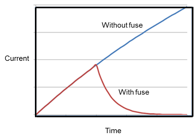
Figure 5 Schematic diagram of “current limiting effect” by fuse
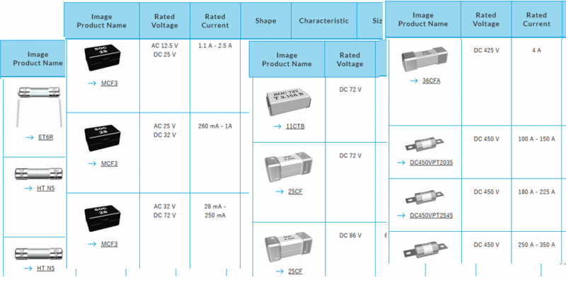
Figure 6 A large choice of electric fuses
(2) Various options
Fuses have a broad product protfolio with different sizes and shapes and different ratings for voltage, current and interruption; some of which are shown in Fig. 6.
If you are uncertain which product to select, please refer to our “Technical Paper: Fuse Selection Procedure” on our website, or, please contact one of our sales representatives.
(3) Small size and low cost
A fuse has a simple structure with a small total number of components as mentioned in (1).
That leads to fuse’s key features: the small size and low cost for its voltage, current, and breaking ratings.
Taking advantages of those key features of fuses, one can manufacture products compactly and at low cost.
Backup with technical data
In addition to the rated values, detailed data such as I-t curve, I2t-t curve, and temperature rerating curve are shown in the product specifications of our fuses so that they can be used for safety circuit design.
These data have been rigorously acquired using a series of fuse test facilities in our fuse testing room shown in Fig. 7.
For details of these test facilities, please refer to “Technical paper: Guide to test facilities”.
If you require additional data not included in the product specifications, please contact us.
When the circuit current level changes upon modification of your circuit design, it will be necessary to adjust the safety design to this change as well.
Otherwise, some trouble may occur.
If you are using, in your circuit, fuses with a wide variety of product lineups and ratings as shown in Fig. 6, you will be able to ensure safety by referring to the fuse product specification data sheets to change the ratings of the fuses.
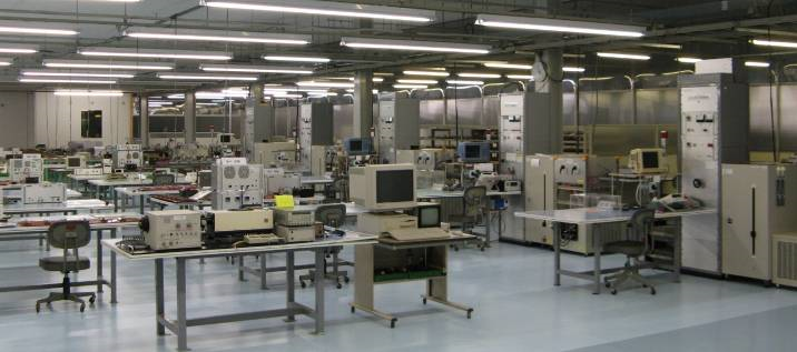
Figure 7 Fuse testing room
Finally
We hope this technical paper will help you choose the components for the circuit you are designing.
If you have read this paper and are interested in fuses, and if you need more information about fuses to proceed with your consideration, please do not hesitate to contact us.